SCADA Multi-Protocol Simulator User Manual
Introduction
VestaTel SCADA Multi-Protocol Simulator runs on Windows and implements master / slave, client / server role of SCADA protocols: IEC 60870-5-104, IEC 60870-5-101, IEC 61850/MMS, DNP3 and MODBUS
Overview of Features
IEC 104 Protocol, IEC 101 Protocol
IEC 60870-5-104 Master / IEC 60870-5-104 Slave
IEC 60870-5-101 Master / IEC 60870-5-101 Slave
IEC 104 Link Layer runs over TCPIP
IEC 101 over RS232 Serial and over TCPIP
IEC 101 Balanced / Unbalanced Link Mode
Station Initialization, Clock Synchronization
Data Acquisition, Events Acquisition
Cyclic / Background / Spontaneous Transmission
General Interrogation, Command Transmission
Time Tagged and Time Untagged Commands
IEC 61850/MMS Protocol
IEC 61850 IED Client / IEC 61850 Server
Runs over TCPIP
Supports edition 2 of the IEC 61850 standard
Data model discovery, data object polling
Control commands: Direct Operate, Select-Operate
Suports all major MMS data types, bool, integer, float, string, etc
Supports parsing and displaying Timestamps, quality
DNP3 Protocol
DNP3 Master / DNP3 Slave
Runs over RS232 Serial and over TCPIP
Solicited (Polled) and Unsolicited Mode
Initial and Periodic Time Synchronization
Periodic and demand Integrity Poll, Event Poll
Binary Output Command, Analog Output Command
MODBUS Protocol
MODBUS Master / MODBUS Slave
MODBUS RTU over RS232 Serial
MODBUS TCP mode over TCPIP
Discreet Input Register, Coil Registers
Holding Registers, Input Registers
Write Single Coil, Write Multiple Coils
Write Single Register, Write Multiple Registers
HART Protocol
HART Communication Protocol (Highway Addressable Remote Transducer) master side only is supported in the current version of software. The simulator implements the physical layer over RS232 serial port, data link Layer
and application layer. All device dynamic variables (PV, SV, TV and QV) are polled periodically and their value is displayed in the points view. The implementation is done according to standards HCF_SPEC-127, Revision 7.1,
(HART Communication Protocol, Universal Command Specification), HCF_SPEC-99, Revision 9.0 (HART Communication Protocol, Command Summary Specification)
Installation Procedure
Download VestaTel SCADA Mult-Protocol Simulator install executable from Here
Run the installation program, read and accept the Software License Agreement and click Next.
At the end of installation click "Finish"
By default the files are installed into c:\VestaTel-Scadasim folder
You can run the application from Windows Search or Start panel or directly from the installation folder
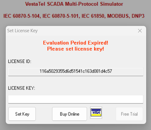
Licensing
Evaluation Mode and Full Mode
If you have not yet purchased the software and set the license key, the software shall run in evaluation mode
Evaluation Period is limited to 7 days.
You can set the license key when the "Set License Key" dialog is displayed. It is shown at startup or each time when license is detected invalid or expired
You receive the license key by email when you purchase the software. To purchase the software click "Buy Online" button in the same dialog window
During operation you can also display this dialog via main menu by clicking "About" -> "Register / Buy Online"
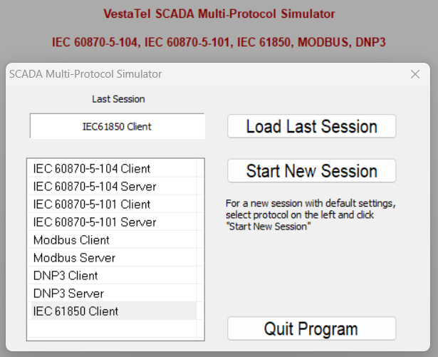
Quick Start
SCADA Protocol Selection
When you start the program it shows the protocol selection window
Unless the program is started for the first time, you can click "Load Last Session" to load the last used protocol configuration
Otherwise you can select and click on the required protocol and then click "Start New Session"
At run time you can bring up the same dialog window via main menu "Tools" -> "Select Protocol"
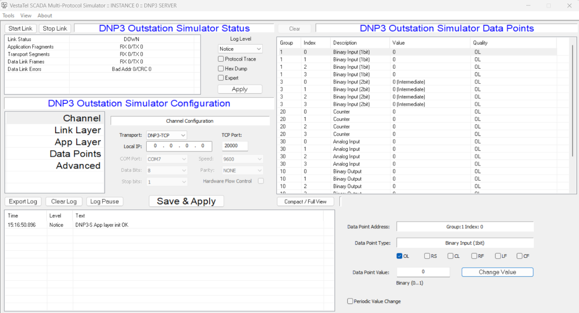
Main Program Screen
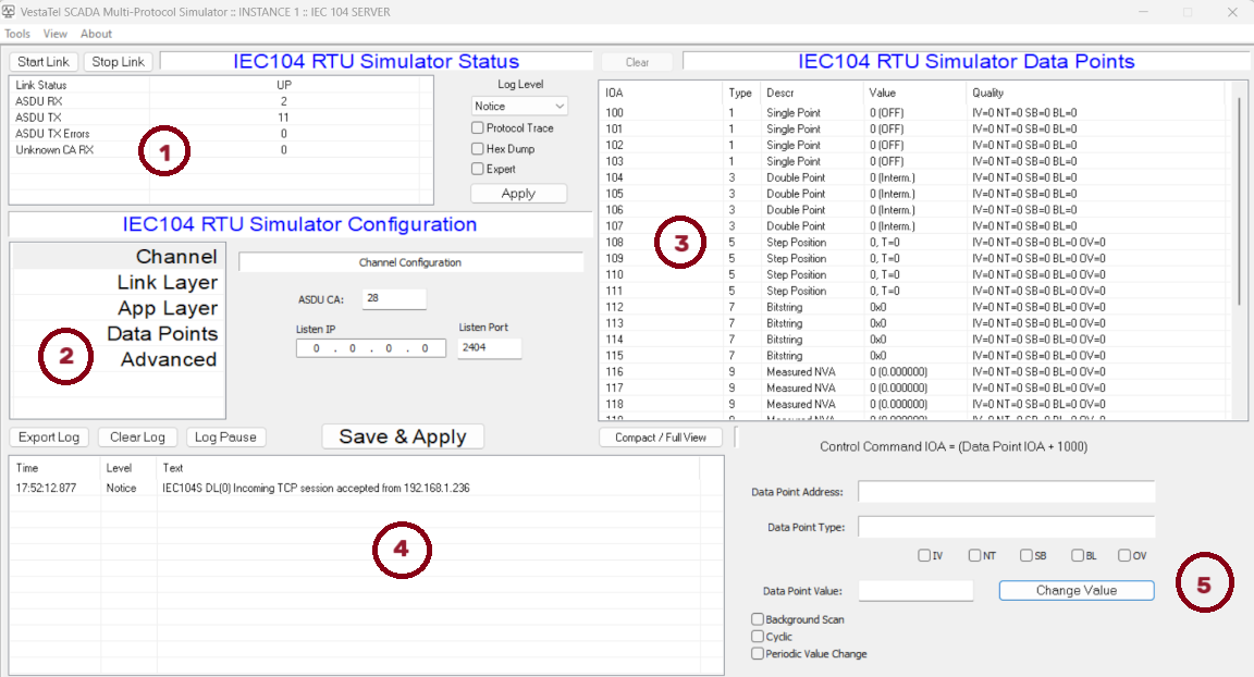
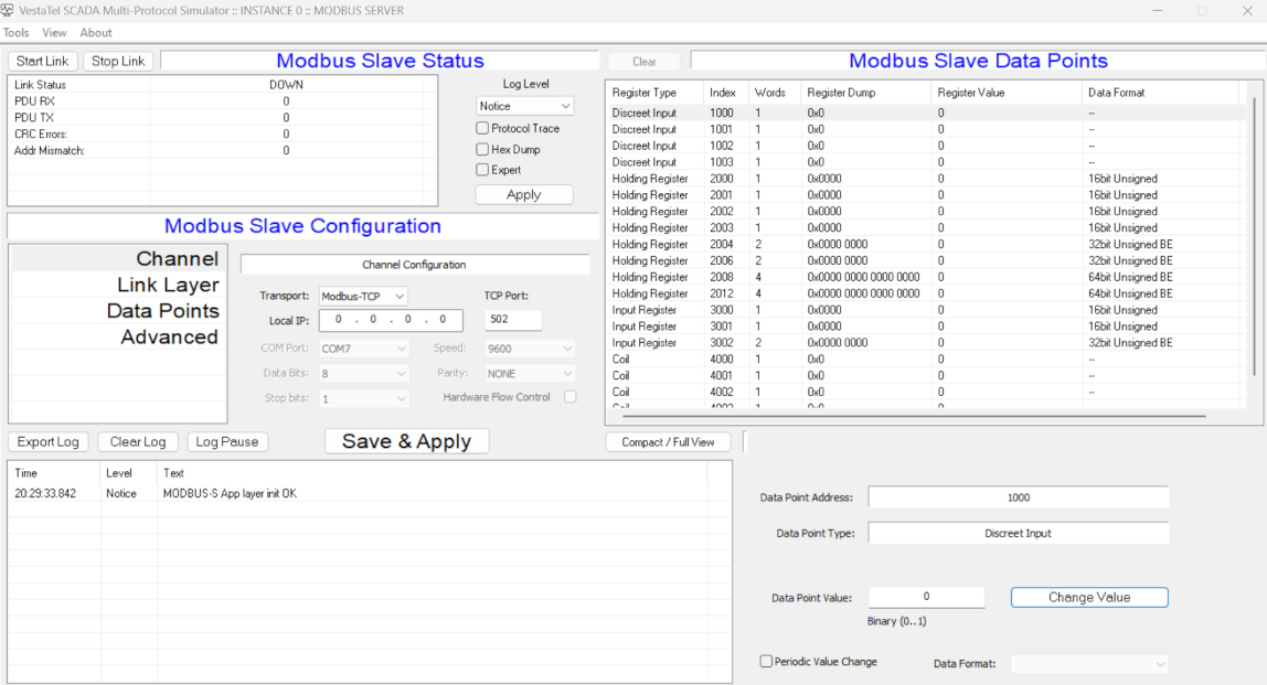
Slave Side Protocols
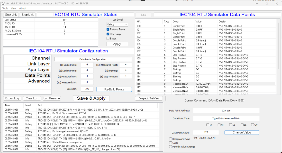
The example below shows the IEC 60 870-5-104 Slave Simulator screen
Description of main control areas
(1) Link Status and Statistic counters
(2) Protocol Configuration
(3) Data Points Window
(4) Log window
(5) Selected Data Point Window
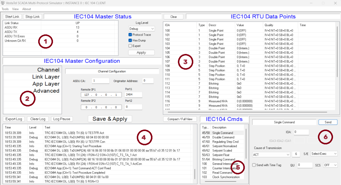
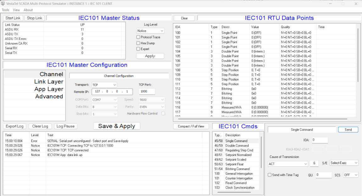
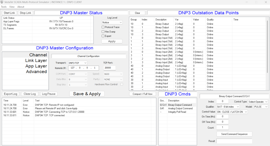
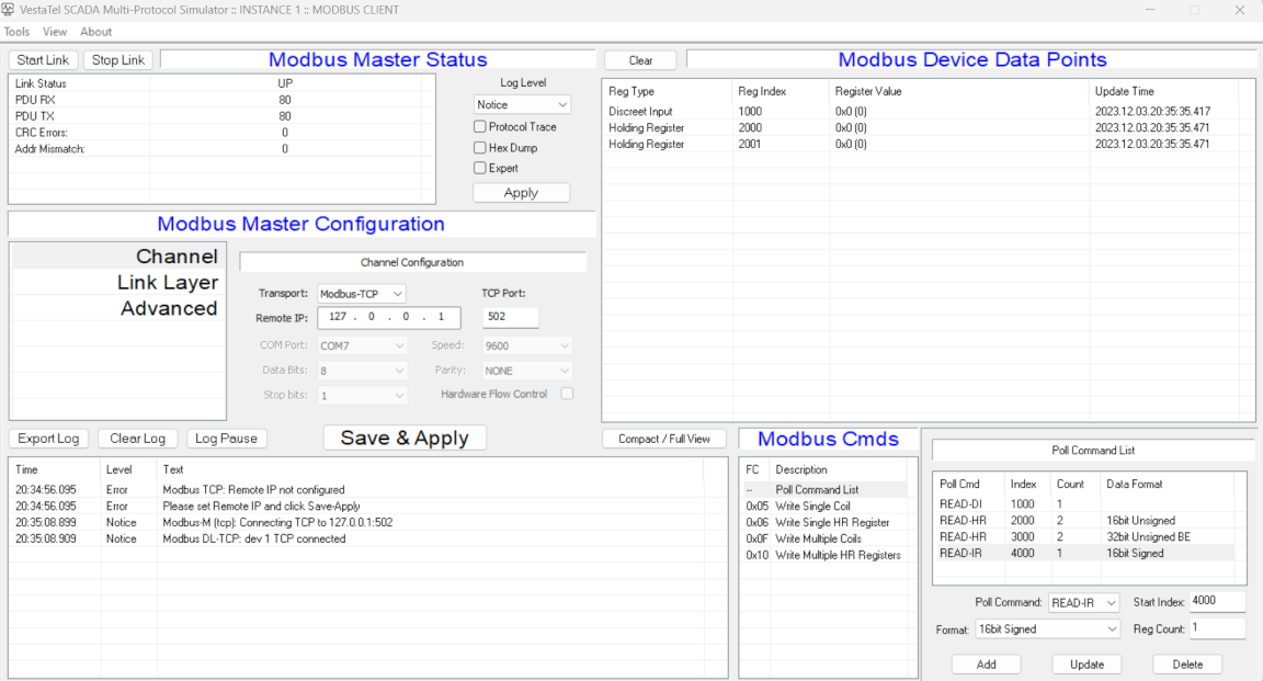
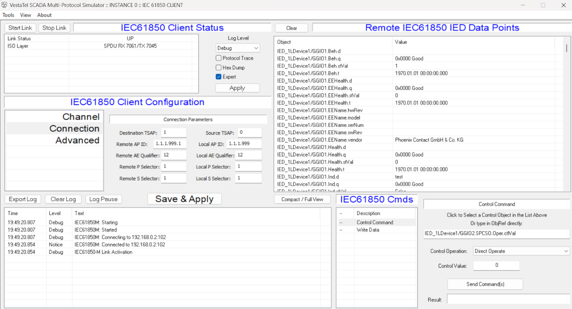
Master Side Protocols
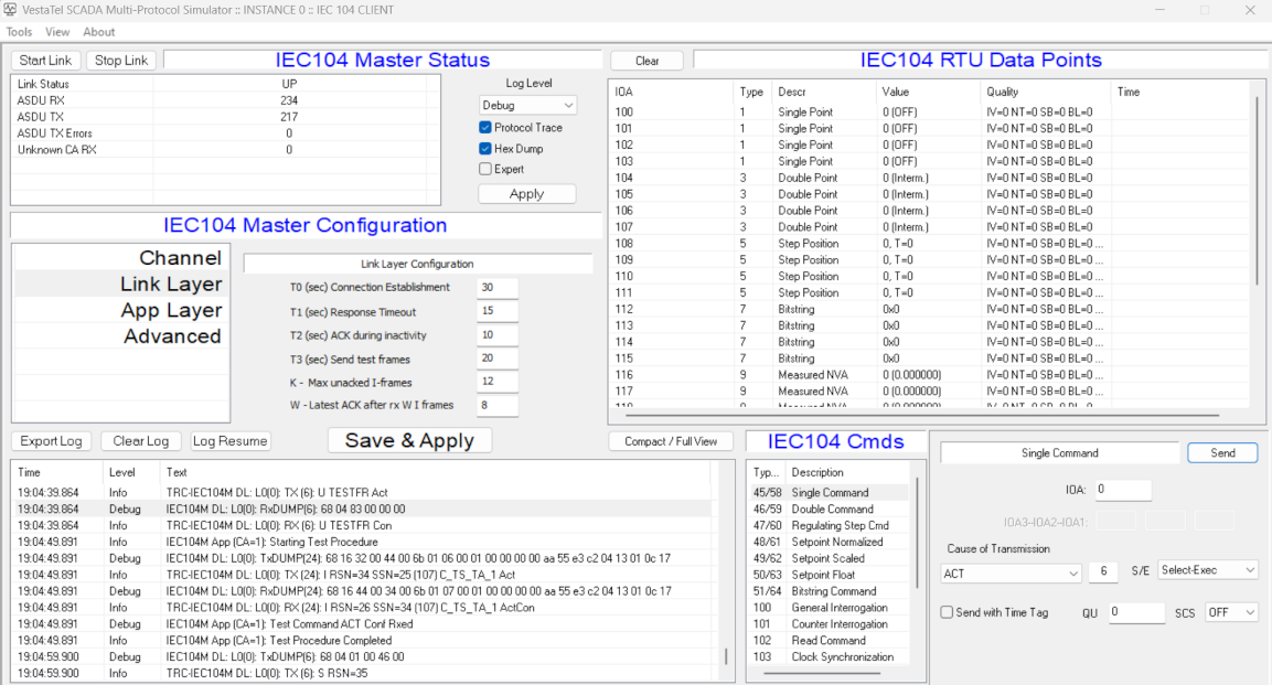
The example below shows the IEC 60 870-5-104 Master Simulator screen
Description of main control areas
(1) Link Status and Statistic counters
(2) Protocol Configuration
(3) Data Points Window
(4) Log window
(5) Command Window
(6) Selected Command details
Configure all required settings in the Protocol configuration tabs / sections on the left. Changing between tabs saves the settings. Every time you click "Save & Apply" configuration is saved and the protocol is re-started
IEC 60870-5-104 Slave
Channel Configuration
ASDU CA - Sets ASDU Common Address as specified in the IEC 60870-5-101. Acceptable values are from 1 to 65534. The same value must be configured in the IEC 104 master for successfull communication
Listen IP - Local IP address on which the IEC104 slave shall accept incoming TCP connections from IEC104 Master
Listen Port - Local TCP port number on which the IEC104 slave shall accept incoming TCP connections from IEC104 Master. The same number must be configured in the corresponding IEC104 client parameter, default is 2404
Link Layer Configuration
In this tab standard IEC 104 data link parameters as specfiied in IEC 60870-5-104 are configured. Timer values are given in seconds
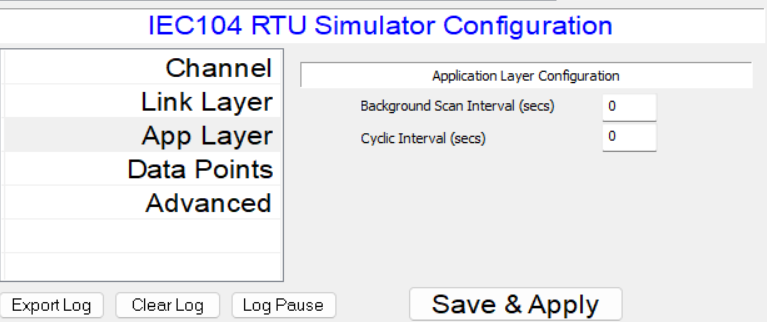
Application Layer Configuration
Selected data point
Background Scan Interval - sets the frequency in seconds of sending data point messages with cause of transmission 2 (Background Scan). When set to 0, background scan sending is disabled for all points.
Only data points that are configured for sending Background Scan are sending these messages. To select a data point for background scan, first choose the required point in the Data Points window in the top right part of the main screen,
then click on that point and check tickbox "Background Scan" in the data point window in the bottom right part of main screen
Cyclic Interval - sets the frequency in seconds for sending data point messages with cause of transmission 1 (Cyclic). When set to 0, cyclic transmission is disabled. Measured value data points can be sent periodically using this procedure.
To select a data point for cyclic transmission, first choose the required point in the Data Points window in the top right part of the main screen,
then click on that point and check tickbox "Cyclic" in the data point window in the bottom right part of main screen
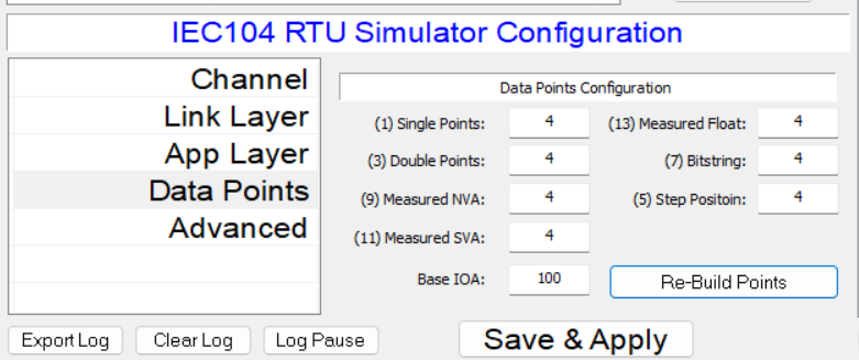
Data Points Configuration
This tab contains configuration of the number of data points of specific type IDs that shall be emulated and that shall appear in the data points window on the right top of the screen.
Base IOA field defines the starting IOA (Information object address) for the first data point. Please note that the maximum total number of points currently supported is 1024
When the desired number of points of each type is set, click "Re-Build Points" to apply new configuration
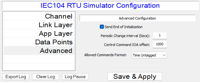
Advanced Configuration
Send End of Initialization - Controls whether or not the slave simulator sends message type ID 70 (M_EI_NA_1) - End of Initialization after data link connection is established
Periodic Change Interval - sets the frequency at which the data point values change (increment) if selected for Periodic Value Change. When set to 0, no data points are changed periodically. To select a data point for
peridic change, select it the data point list in the top right, then tick checkbox "Periodic Value Change" in the selected data point window in the right bottom of the main screen. When a point is changed periodically
its value is incremented, written into configuration and an event message with cause of transmission Spontaneous is sent to the connected Master
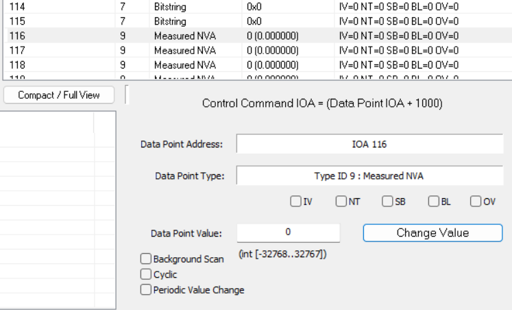
Control Command IOA offset - defines IOA (information object address) to which the connected Master can send a command to change the addressed data point value.
For example to change a Single Point Information point at IOA 100, the Master should send the Single Command to IOA 1100 if the control offset is configured at 1000
Allowed Command Format - Sets the format of control commands accepted by the slave simulation to Time Tagged or Time untagged
IEC 60870-5-104 Master
Channel Configuration
ASDU CA - Sets ASDU Common Address as specified in the IEC 60870-5-101. Acceptable values are from 1 to 65534. The same value must be configured in the IEC 104 slave for successfull communication
Originator Address - Sets the OA (originator address) field that is the second byte of the cause of transmission part in the IEC104 ADSU packets
Remote IP1 - Remote IP address to which the IEC104 master shall connect, Remote IP2 can be used for redundancy
Port1 - Remote TCP port number to which the IEC104 master shall connect. The same number must be configured in the corresponding IEC104 server parameter, default is 2404. Port2 can be used for redundancy
Link Layer Configuration
In this tab standard IEC 104 data link parameters as specfiied in IEC 60870-5-104 are configured. Timer values are given in seconds
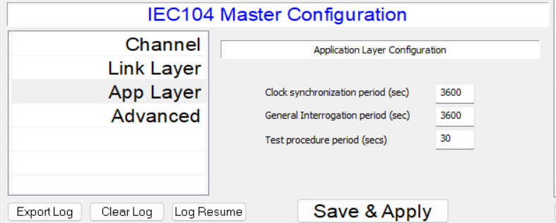
Application Layer Configuration
Clock syncrhronization period - sends the frequncy in seconds of performing periodic clock synchronization procedure
General interrogation period - sets the frequency in seconds of performing periodic general interrogation procedure
Test procedure period - sets the frequency in seconds of performing test procedure
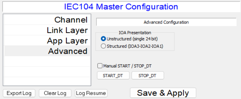
Advanced Configuration
IOA Presentation - sets the view (structured as 3 bytes or unstructured as 24 bit integer) of IOA (information object addresses in the IOA column in the data points list and in the commands
Start DT - Stop DT - Allows manual sending of START DT and STOP DT packets to the slave station
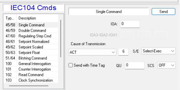
IEC 104 Master Commands
To send the required command, select one from the IEC104 Cmds list in the bottom right of the screen, then setup the IOA and value fields and click Send button
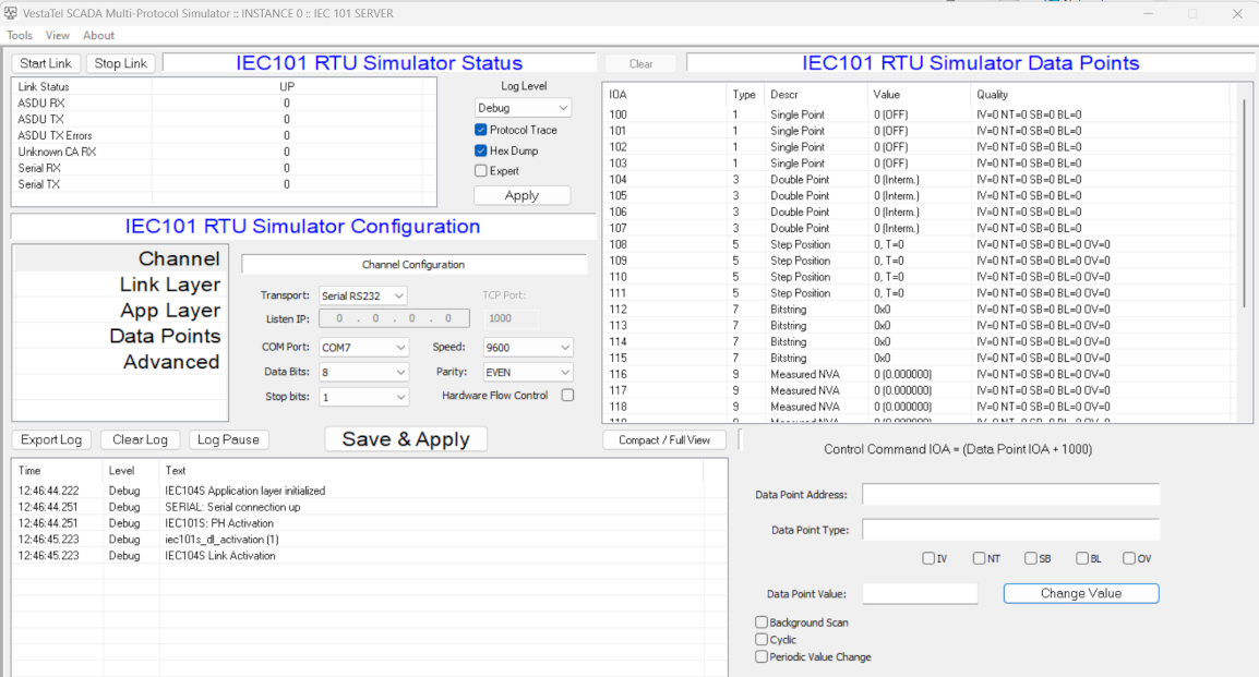
IEC 60870-5-101 Slave
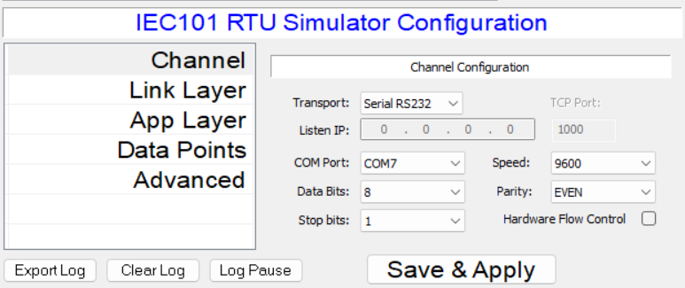
Channel Configuration
VestaTel SCADA Multi-Protocol Simulator in IEC101 slave mode can operate over RS232 serial interface or over TCP/IP. To select / switch between serial and TCP/IP choose Transport selector as required.
Note that when COMx ports are present they are shown in the COM Port selector. If no serial interfaces are detected that list is empty
Transport: Selects Seral RS232 or TCP/IP transport for IEC 60870-5-101 protocol
Listen IP: When TCP/IP transport is selected, sets the listening IP address
TCP Port: When TCP/IP transport is selected, sets the listening TCP port
COM Port: Sets the COM port number for operation over RS232
Data Bits: Sets number of serial data bits
Stop Bits: Sets number of serial stop bits
Speed: Sets serial interface speed
Parity: Sets serial interface parity
Hardware Flow Control: Enables RTS/CTS flow control
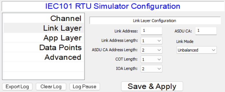
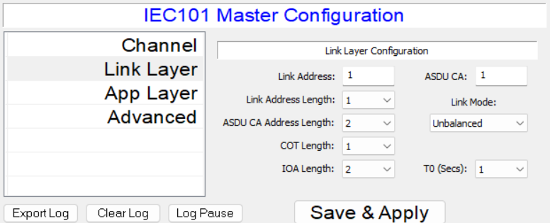
Link Layer Configuration
Link Address: Sets IEC 60870-5-101 Link address value
ASDU CA: Sets IEC 60870-5-101 ASDU Common Address value
Link Address Length: Sets IEC101 link address length
ASDU CA Length: Sets IEC101 ASDU Common Address length
COT length: Sets cause of transmission length
IOA Lenth: Sets information object address length
Link Mode: Sets IEC101 link mode (currently only Unbalanced is supported)
Application Layer Configuration
See IEC104 Server Application Layer Configuration
Data Points Configuration
See IEC104 Server Data Points Configuration
Advanced Configuration
See IEC104 Server Advanced Configuration
IEC 60870-5-101 Master
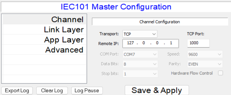
Channel Configuration
VestaTel SCADA Multi-Protocol Simulator in IEC101 master mode can operate over RS232 serial interface or over TCP/IP. To select / switch between serial and TCP/IP choose Transport selector as required.
Note that when COMx ports are present they are shown in the COM Port selector. If no serial interfaces are detected that list is empty
Transport: Selects Seral RS232 or TCP/IP transport for IEC 60870-5-101 protocol
Remote IP: When TCP/IP transport is selected, sets the remote IP address
TCP Port: When TCP/IP transport is selected, sets the remote TCP port
COM Port: Sets the COM port number for operation over RS232
Data Bits: Sets number of serial data bits
Stop Bits: Sets number of serial stop bits
Speed: Sets serial interface speed
Parity: Sets serial interface parity
Hardware Flow Control: Enables RTS/CTS flow control
Link Layer Configuration
Link Address: Sets IEC 60870-5-101 Link address value
ASDU CA: Sets IEC 60870-5-101 ASDU Common Address value
Link Address Length: Sets IEC101 link address length
ASDU CA Length: Sets IEC101 ASDU Common Address length
COT length: Sets cause of transmission length
IOA Lenth: Sets information object address length
Link Mode: Sets IEC101 link mode ro Balanced or Unbalanced
T0 Secs: Sets IEC101 link layer timer T0 value
DNP3 Slave
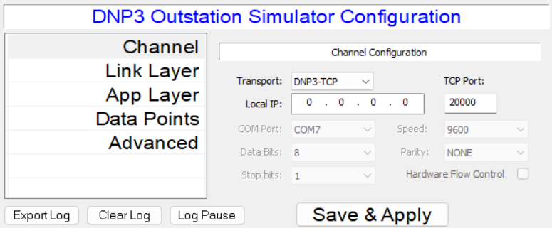
Channel Configuration
Transport: Selects Seral RS232 or TCP/IP transport for DNP3 protocol
Local IP: When TCP/IP transport is selected, sets the local IP address
TCP Port: When TCP/IP transport is selected, sets the local TCP port
COM Port: Sets the COM port number for operation over RS232
Data Bits: Sets number of serial data bits
Stop Bits: Sets number of serial stop bits
Speed: Sets serial interface speed
Parity: Sets serial interface parity
Hardware Flow Control: Enables RTS/CTS flow control
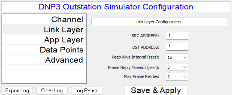
Link Layer Configuration
SRC ADDRESS: DNP3 link source address
DST ADDRESS: DNP3 link destimation address
Keep Alive Interval: DNP3 link keep alive timeout
Frame Reply Timeout: DNP3 link frame reply timeout
Max Frame Retries: Maximum number of DNP3 link frame re-transmits
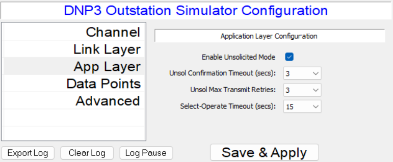
Application Layer Configuration
Enable Unsolicited Mode: Enables or disables Unsolicited Response Mode
Unsol Cofirmation Timeout: Timeout value for waiting for unsolicited confirmations
Unsol Max transmit retries: Maximum number of retransmit attempts for unsolicited mode
Select Operate Timeout: Sets maximum time allowed between Select and Operate commands
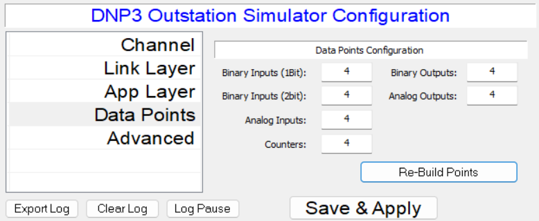
Data Points Configuration
This tab contains configuration for the number of DNP3 Slave simulator data points of different types: Binary Inputs (single and double bit), Analog Inputs, Binary Outputs and Analog Outputs.
To change the default data point setup, change the number of points as needed and click "Re-Build Points". Note that the total maximum number of data points supported is 1024.
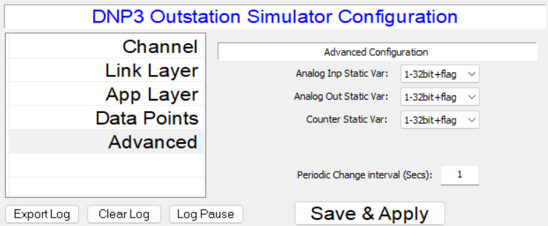
Advanced Configuration
Analog Inp Static Var: Sets the variation number used for static DNP3 Inputs
Analog Out Static Var: Sets the variation number used ror static DNP3 Outputs
Counter Static Var: Sets the variation number used for static Counters
Periodic Change Interval: Sets the interval in seconds for generating periodic change (incrementation) in the selected data points
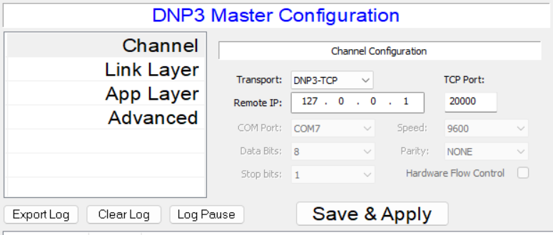
DNP3 Master
Channel Configuration
Transport: Selects Seral RS232 or TCP/IP transport for DNP3 protocol
Remote IP: When TCP/IP transport is selected, sets the remote IP address
TCP Port: When TCP/IP transport is selected, sets the remote TCP port
COM Port: Sets the COM port number for operation over RS232
Data Bits: Sets number of serial data bits
Stop Bits: Sets number of serial stop bits
Speed: Sets serial interface speed
Parity: Sets serial interface parity
Hardware Flow Control: Enables RTS/CTS flow control
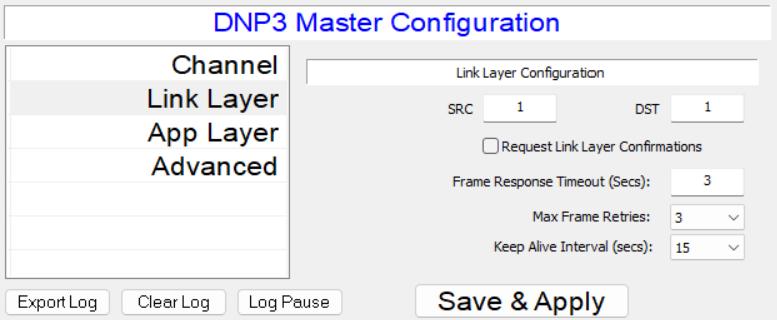
Link Layer Configuration
SRC ADDRESS: DNP3 link source address
DST ADDRESS: DNP3 link destimation address
Keep Alive Interval: DNP3 link keep alive timeout
Frame Reply Timeout: DNP3 link frame reply timeout
Max Frame Retries: Maximum number of DNP3 link frame re-transmits
Request Link Layer Confirmations: Enables or Disables link layer confirmations
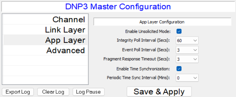
Application Layer Configuration
Enable Unsol Mode: Enables or disables unsolicited response mode in the DNP3 slave
Integrity Poll Interval: Sets interval in seconds for sending integrity poll to DNP3 slave
Event Poll Interval: Sets interval in seconds for sending periodic event polls to DNP3 slave
Fragment Response Timeout: Sets response timeout in seconds for receiving response fragments from DNP3 slave
Enable Time Synchronization: Enables or disables time synchronization procedure
Periodic Time Syncrhonization Interval: Sets periodic time synchronization interval in seconds, 0=periodic time synchronization off.
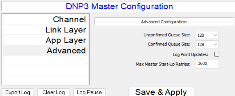
Advanced Configuration
Unconfimed Queue Size: Sets the frame queue size for unconfirmed transmit fragments
Confirmed Queue Size: Sets the frame queue size for confirmed transmit fragments
Log Point Updates: Enables or disables logging data point updates
Master startup retries: Sets the maximum number of times to re-try failed Master startup procedure
Modbus Server
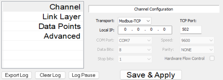
Channel Configuration
Transport: Selects Seral RS232 or TCP/IP transport for Protocol protocol
Local IP: When TCP/IP transport is selected, sets the local IP address
TCP Port: When TCP/IP transport is selected, sets the local TCP port
COM Port: Sets the COM port number for operation over RS232
Data Bits: Sets number of serial data bits
Stop Bits: Sets number of serial stop bits
Speed: Sets serial interface speed
Parity: Sets serial interface parity
Hardware Flow Control: Enables RTS/CTS flow control
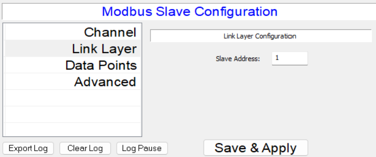
Link Layer Configuration
Slave Address: Sets the Modbus slave address
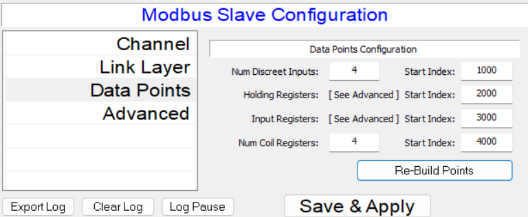
Data Points
This configuration tab contains the configuration fields that define the number of Modbus data points emulated in Modbus slave simulator mode by the application
Set the required number of registers of each type and their start index and click Re-Build Points when done. The total number of points supported is 1024
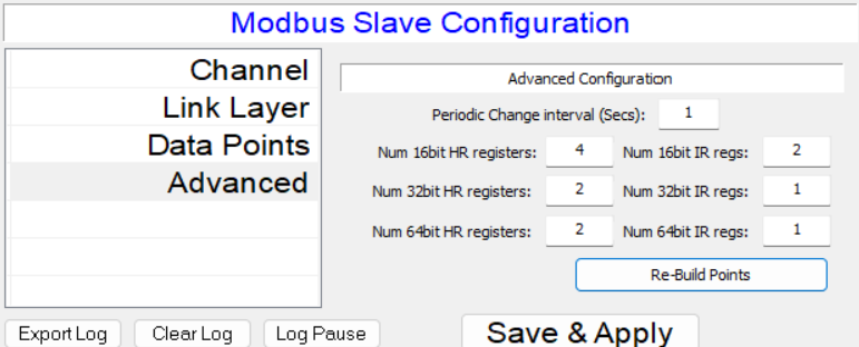
Advanced Configuration
This configuration tab contains the configuration fields that define the number of Modbus data points and specific data formats of HR and IR registers emulated in Modbus slave simulator mode by the application
16, 32 and 64 bit sized registers can be defined here. Once defined the format can be further changed for each register in the data points list as signed, insigned, little endian, big endian, integer or float, etc.
Set the required number of registers of each type and their start index and click Re-Build Points when done. The total number of points supported is 1024
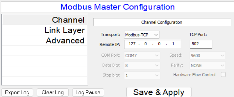
Modbus Client
Channel Configuration
Transport: Selects Seral RS232 or TCP/IP transport for Modbus protocol
Remote IP: When TCP/IP transport is selected, sets the remote IP address
TCP Port: When TCP/IP transport is selected, sets the remote TCP port
COM Port: Sets the COM port number for operation over RS232
Data Bits: Sets number of serial data bits
Stop Bits: Sets number of serial stop bits
Speed: Sets serial interface speed
Parity: Sets serial interface parity
Hardware Flow Control: Enables RTS/CTS flow control
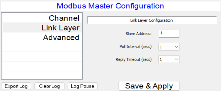
Link Layer Configuration
Slave Address: Sets the Modbus slave address
Poll interval: Sets the slave polling interval in seconds
Reply Timeout: Sets the reply timeout in seconds
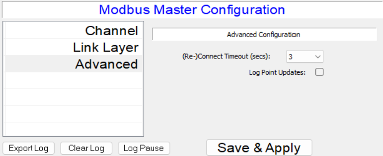
Advanced Configuration
Re-Connect timeout: Sets TCP or serial re-connect timeout in seconds
Log point updates: Enables or disables logging of data point updates
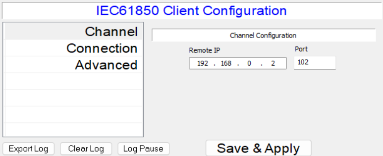
IEC 61850 Client
Channel Configuration
Remote IP: sets the remote IP address to connect to
Port: sets the remote TCP port to connect to
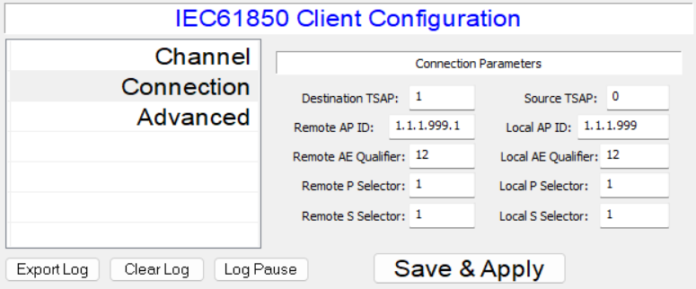
Connection Parameters
Destination TSAP: Destination transport access point number
Source TSAP: Source transport access point number
Remote AP ID, Local AP ID: Local and remote Access Point ID
Remote AE Qualifier, Local AE Qualifier:
Remote P Selector, Local P Selector:
Remote S Selector, Local S Selector:
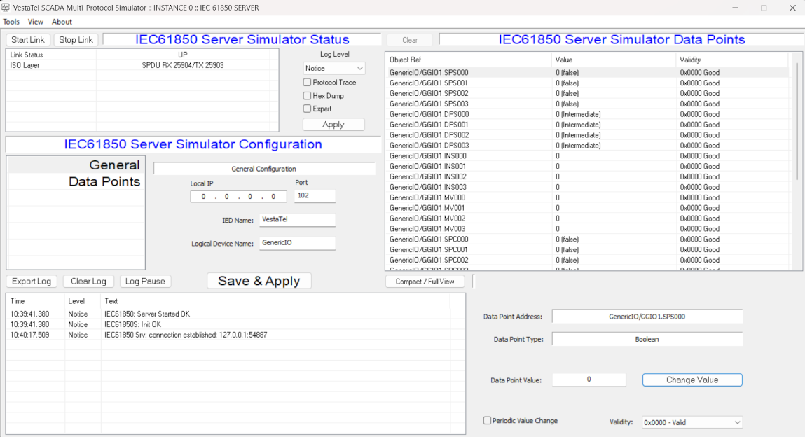
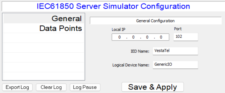
IEC 61850 Server
Channel Configuration
Local IP: sets the local IP address on which IEC 61850 server listens for incoming connections
Port: sets the local TCP port on whic IEC 61850 server listens for incoming connections
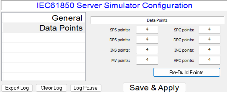
Data Points
SPS points: Sets number of Single Point Status data points
DPS points: Sets number of Double bit Point Status data points
INS points: Sets number of Integer Status data points
MV points: Sets number of Measured Value data points
SPC points: Sets number of Single Point Controllable Status data points
DPC points: Sets number of Double bit Controllable Status data points
INS points: Sets number of Controllable Integer Status data points
APC points: Sets number of Controllable Analog Points